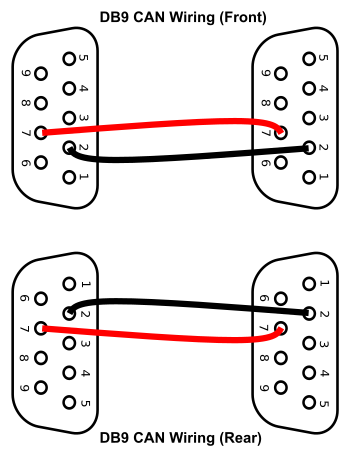
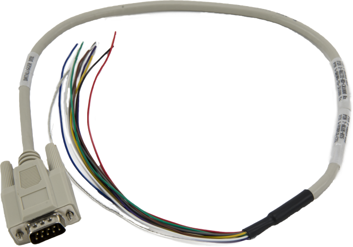
Db9 Pin Color Code
Looking for a way to transmit data from one device to another quickly and securely? Thanks to RS232 serial port monitoring hardware, you should have no trouble capturing data and overcoming many of the latency and time-tagging problems commonly associated with traditional dual COM port monitoring solutions.
Restore Your Aston Martin Finish In Two Steps Select Your Aston Martin's Color (Step One). AutomotiveTouchup paint products are custom mixed to perfectly match the color of your 2003 Aston Martin DB9 using a basecoat/clearcoat system just like factory specs. To insure a proper match, you’ll need to know your vehicle’s color code so you can find it on the chart below. B - 25-pin 2-row serial or parallel connector - also 44-pin high-density 3-row. C - 37-pin connector - sometimes found on multi-port serial or data acquisition boards. D - 50-pin connector - a little longer than C, but three rows using the same pins as the 2-row connectors. E - 9-pin 2-row serial - also 3-row VGA. So a DB9 is more properly a DE-9P.
RS232 serial port monitoring hardware stands out for a number of reasons, including its 9 pin RS232 pinout. This pinout can make a world of difference for successful RS232 serial communications. Thus, it is important to understand how the 9 pin RS232 cable pinout can affect the flow of serial data between devices.
Db9 Cable Color Code
Here’s a closer look at how the 9 pin RS232 pinout works and what it means for users who want to transmit data between devices safely and efficiently.
Db9 Pin Color Code
What Is an RS232 9 Pin Pinout?
RS232 monitoring hardware establishes a connection between data terminal equipment (DTE) and data communication equipment (DCE). In order to link these devices, an RS232 D9 pinout is essential, as this pinout will allow you to connect two devices successfully.
An RS232 pinout 9 pin cable features nine pins:
1. Data Carrier Detect – After a data terminal is detected, a signal is sent to the data set that is going to be transmitted to the terminal.
2. Received Data – The data set receives the initial signal via the receive data line (RxD).
3. Transmitted Data – The data terminal gets a signal from the data set, a confirmation that there is a connection between the data terminal and the data set.
4. Data Terminal Ready – A positive voltage is applied to the data terminal ready (DTR) line, a sign that the data terminal is prepared for the transmission of data.
5. Signal Ground – A return for all the signals on a single interface, the signal ground (SG) offers a return path for serial communications. Without SG, serial data cannot be transmitted between devices.
6. Data Set Ready – A positive voltage is applied to the data set ready (DSR) line, which ensures the serial communications between a data terminal and a data set can be completed.
7. Request to Send – A positive voltage indicates the request to send (RTS) can be performed, which means the data set is able to send information to the data terminal without interference.
Db9 Pin Color Code For Trailer Hook Up
8. Clear to Send – After a connection has been established between a data terminal and a distant modem, a clear to send (CS) signal ensures the data terminal recognizes that communications can be performed.
Db9 Pin Color Code Blue
9. Ring Indicator – The ring indicator (RI) signal will be activated if a modem that operates as a data set detects low frequency. When this occurs, the data terminal is alerted, but the RI will not stop the flow of serial data between devices.
Understanding the ins and outs of the 9 pin RS232 cable pinout can be challenging for even experienced design services professionals. But with support from a proven engineering team, you can optimize the transmission of data via a RS232 9 pin pinout.
Stratus Engineering supplies a broad array of RS232 hardware monitoring solutions, along with application expertise and extensive hardware and software engineering experience. To learn more how we support electronics and software for embedded systems, please contact us today at 858-663-1841.
6 pin RJ11, RJ14, RJ25female connector at the phone and wallet socket (Jack).
6 pin RJ11, RJ14, RJ25male connector at the cable (Plug).

The six-position plug and jack commonly used for telephone lineconnections may be used for RJ11, RJ14 or even RJ25, all of whichare actually names of interface standards that use this physicalconnector. The RJ11 standard dictates a 2-wire connection, whileRJ14 uses a 4-wire configuration, and RJ25 uses all six wires. TheRJ abbreviations, though, only pertain to the wiring of the jack(hence the name “registered jack”); it is commonplace but notstrictly correct to refer to an unwired plug connector by any ofthese names. Typically you’ll find the RJ-11 and RJ-14 on yourPlain Old Telephone Service (POTS) though your RJ25 typically isfound in an Integrated Services Digital Network (ISDN) Line. It isthe communication standards that lets telephone lines to carrydigital, voice, video, and network services.

| position | RJ25 pin | RJ14 pin | RJ11 pin | Pair | T/R | ± | Cat 5e/6 colors | Colors | Old colors |
|---|---|---|---|---|---|---|---|---|---|
| 1 | 1 | 3 | T | + | white/green | white/green | orange | ||
| 2 | 2 | 1 | 2 | T | + | white/orange | white/orange | black | |
| 3 | 3 | 2 | 1 | 1 | R | – | blue | blue/white | red |
| 4 | 4 | 3 | 2 | 1 | T | + | white/blue | white/blue | green |
| 5 | 5 | 4 | 2 | R | – | orange | orange/white | yellow | |
| 6 | 6 | 3 | R | – | green | green/white | blue |

Notes
Db9 Pin Color Code For Spool Gun
- While the old solid color code was well established for pairs 1and 2, there are several conflicting conventions for pair 3. Thecolors shown above were taken from a vendor of “silver satin” flat8-conductor phone cable that claims to be standard. Other 3 pairsolid (old) bellwire cables may substitute white for orange. Atleast one other vendor of flat 8-conductor cable uses the sequenceblue, orange, black, red, green, yellow, brown andwhite/slate.
- Holding the connector in your hand tab side down with the cableopening toward you, the pins are numbered 1-6, left to right.
- In modern structured wiring Cat5e or Cat6 is commonly used inhomes and buildings. The Cat 5e and Cat 6 data lines are often usedfor both voice or data. The color codes above are the standard anddefined within wiring guides.
- The CAT 3 Cable can also be used for the RJ-14 Pinout with thesame color code as the CAT5 and CAT6. The internal pairs to thepinout are trasmit and recieve (1 and 1), while the 2 side pairs (2and 2) are your power.
- The RJ25 is going to be the standardized phone cable for yourISDN (Integrated Services Digital Network) it allows phones such asthe (STE) to carry digital, voice, video, and network services.Though there is an RJ45 port connection, you can implement the RJ25to push all information if the Port has the proper configurationsat the switch. For an RJ25 you’ll need to use CAT5 or CAT6 since aCAT3 is only a 4 wire cable.
Color Code Rgb
References and Sources

Db9 Wiring
- http://en.wikipedia.org/wiki/Registered_jackWikipedia: Registered jack
- http://en.wikipedia.org/wiki/RJ11,_RJ14,_RJ25Wikipedia: RJ11,_RJ14,_RJ25
- http://www.allpinouts.org/index.php/User_talk:Draconim:Cpl Dickerson JM Technical Controller
